Requirements
This guidance relates to installation and safety requirements that must be carried out by Registered Electrical Contractors (RECs) and Licensed Electrical Workers (LEWs) to ensure a safe and compliant battery system installation. LEWs and RECs have various legal obligations to install, be responsible for installation and inspect electrical work and equipment safely under the Electricity Safety Act 1998 (the Act) and the Electricity Safety (General) Regulations 2019.
This guidance is also relevant to Licensed Electrical Inspectors (LEIs) to ensure the completed installation is tested and verified in accordance with the Act and regulations.
As part of the legislative framework, the following Australian Standards are applicable to a battery installation – neutral continuity and multiple earthed neutral (MEN) connection:
- AS/NZS 4777.1:2024 Grid connection of energy systems via inverters, Part 1: Installation requirements.
- Section 5 covers the requirements for the installation of multiple mode inverters (MMI) and references the alternative supply arrangements in AS/NZS 3000 including neutral continuity, earthing arrangements and correct operation of residual current devices (RCDs).
- AS/NZS 3000:2018 Electrical installations (the Wiring Rules).
- Clause 7.3.8.1.1(c) relating to alternate (Stand-by) supplies to an installation states 'Neutral and Earth conductors shall not operate in parallel'.
- Clause 7.3.8.1.2 requires the change-over device for the alternative supply to maintain the continuity of the neutral conductor and operation of the RCD.
The Electricity Safety (General) Regulations 2019.
Regulation 208 defines the requirements for earthing systems. A low voltage electrical installation required to be earthed must have an earthed neutral connection or a multiple earthed neutral (MEN) connection:
- at the main switchboard; or
- at an earth bar or link within a substation; or
- made through an earthing conductor or terminal provided by the electricity supplier.
These requirements are above the manufacturer’s installation instructions. The full text of the Australian Standards can be purchased from the Standards Australia store.
Important: If the manufacturer’s installation instructions require other systems of earthing or neutral continuity they are not to be installed, and further information must be sort from the manufacturer.
Energy Safe carries out targeted audits of these types of installation to ensure they have been installed safely.
Potential risk
Installation of a MMI that provides an alternative supply (stand-alone/backup power) in the event of a grid outage has the potential to create electric shocks.
Where neutral continuity is not maintained there is the potential of causing a voltage rise on the installation earthing system and therefore imposing a voltage on any conductive medium that is connected to the installation electrical earthing system. In this situation a return path for fault currents has not been provided.
Where neutral and earth cables are installed in parallel there is a risk of conductors not being of adequate size to carry fault currents.
Hazards
Energy Safe's audits of battery installations have identified 2 main non-compliances creating hazards in MMI installations:
- MMIs installed without continuity between the main neutral bar and the alternative supply circuit neutrals, negating a fault return path.
- Residential properties have a MEN connection at the main switchboard as required, but were also found to have a second MEN created at the MMI alternative supply output port neutral connection.
Our audits indicate a number of installers are not aware of the minimum safety requirements, as set out in the regulations and standards, and the safety risks created by these situations.
Testing to identify these hazards
Testing to verify the safety of the installation must be carried out by a Licensed Electrical Worker (LEW) and a Licensed Electrical Inspector (LEI).
Firstly, mandatory verification testing must be carried out in accordance with Section 8 of AS/NZS 3000 (the Wiring Rules).
Additional testing shall be carried out to verify the installation ensuring:
- Neutral and Earth Conductors are not operating in parallel (no additional MEN connection exists or is switched within the inverter)
- the installation maintains continuity of Neutral conductors.
Important: Some inverters may create an MEN connection internally when switching over to the alternative supply mode. This is not allowed in Australia and must be identified and disabled. Refer to your manufacturer for details on how to achieve this.
Important safety message
The following tests are performed with the installation and equipment in the energised state. The LEW must ensure:
- a safe test procedure is followed in accordance with AS/NZS 4836:2023 Safe working on or near low-voltage and extra-low voltage electrical installations and equipment
- appropriate PPE is used for the task, including eye protection, gloves, protective clothing, etc.
- the work area and installation are safe to proceed with the testing
- that occupants of the property are not put at risk.
Note: The additional testing should be carried out in the following order, with Test 2 only conducted once Test One is verified to ensure both issues can be identified.
Test One – Test method to confirm MEN only at the main switchboard
Important – ensure you carry out this test in both the normal supply mode and alternative supply mode.
Grid mode test
Using a clamp/tong tester set on Amps:
- Ensure the Main Switch Normal Supply is ON, Inverter Supply Main Switch ON and Alternative Supply circuit breaker is ON, allowing the Inverter and MMI to be powered up and operational.
- Ensure the circuit breakers to the normal loads are OFF – lights, power, stoves, A/C etc off.
- Ensure you have a load on the alternative supply circuit, for example a kettle on, or a refrigerator running, etc.
- Test for current flow in the alternative supply Active conductor.
Record the result, for example – 2.0 A (total current flowing in the alternative supply circuit). - Test for current flow in the alternative supply Neutral conductor.
Compliant test result – Same value as recorded on the backup active. - Now test the current flow in the earth conductor connected to the main earth bar or MEN connection.
Compliant test result: Zero (0) Amps
Note: If a current is recorded on the earth conductor, this may indicate an additional MEN connection within the inverter, causing the inverter earth and neutral to operate in parallel.
Alternative Supply mode test
Using a clamp/tong tester set on Amps:
- Ensure the Main Switch Normal Supply is OFF, with the alternative supply ON.
- Ensure you have a load on the alternative supply circuit, for example turn a kettle on, or have a refrigerator running, etc.
- Test for current flow in the alternative supply Active conductor.
Record the result – for example: 2.0 A (total current flowing in the alternative supply circuit). - Test for current flow in the alternative supply Neutral conductor.
Compliant Test Result – Same value as recorded on the backup neutral. - Now test the current flow in the earth conductor connected to the main earth bar or MEN connection.
Compliant Test Result: Zero (0) Amps.
Note: If a current is recorded on the earth conductor, this may indicate an additional MEN connection within the inverter, causing the inverter earth and neutral to operate in parallel.
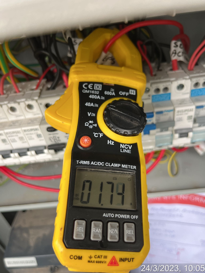 | 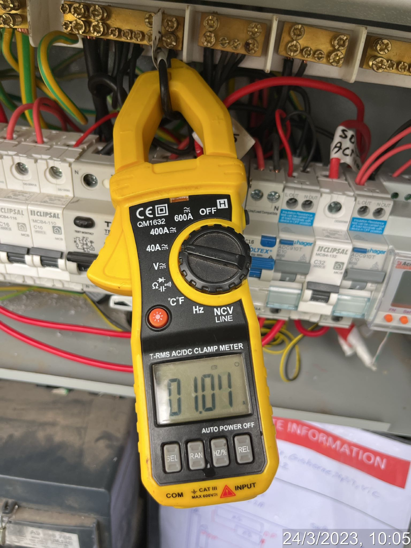 | 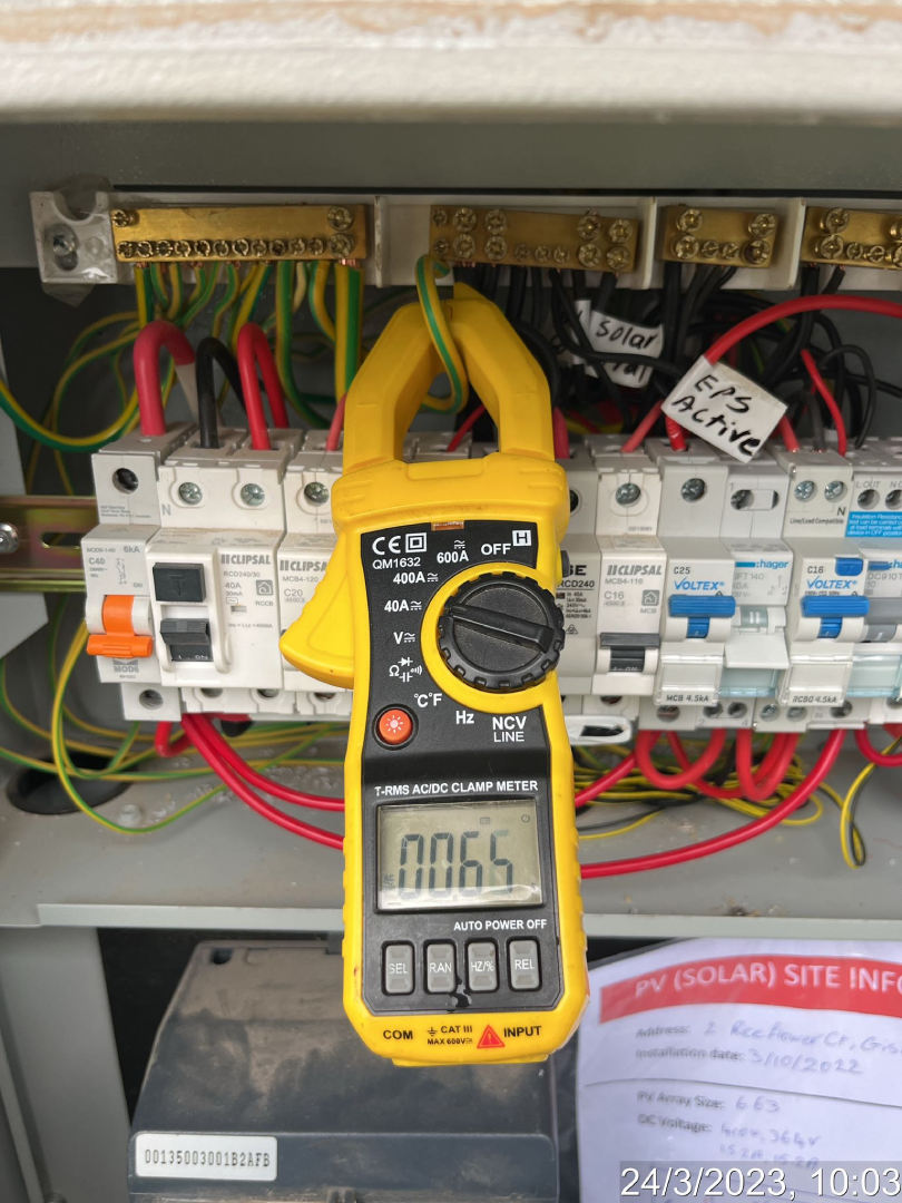 |
Images courtesy of TechSafe Australia acting under the Solar Victoria battery audit program.
Above images shows a non-complaint installation as the current flow through the Active conductor is divided between the Earth and Neutral conductors, indicating a Neutral/Earth connection within the multiple mode inverter (MMI) and allowing the Neutral and Earth conductors to operate in parallel.
Test 2 – Test method to confirm continuity of neutral conductors
With your Multi-meter/Voltage Tester set on AC Volts:
- Ensure the Main Switch Normal Supply CB is OFF, with the Alternative Supply CB ON.
- Test between the Main Earth Bar and the alternative supply Neutral bar/conductors.
Compliant Test Result: Zero (0) Volts. - Now test between the Main Earth Bar and the alternative supply Active conductors.
Compliant Test Result: 230 Volts.
Notes
- If a voltage is recorded on the alternative supply Neutral bar/conductors, this indicates the neutral conductors are not continuous to the properties Main Neutral.
- Be aware – continuity testing between the Main Neutral Bar and the alternative supply Neutral Bar may provide a pass test to indicate continuity in either the de-energised or grid supply states, but then may not maintain continuity when switched to the alternative supply (Stand-alone/backup) modes.
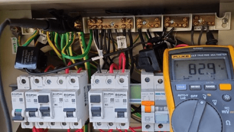
Image Courtesy of TechSafe Australia acting under the Solar Victoria battery audit program.
The above image shows a non-complaint installation as there is voltage tested on the alternative supply Neutral Bar, indicating neutral continuity has not been maintained in the alternative supply mode, recording a potential voltage of 82.9 V a.c.
Summary
- Carry out mandatory verification testing in accordance with Section 8 of AS/NZS 3000: 2018 Electrical installations (the Wiring Rules).
- Ensure the MEN connection is at the main switchboard (or compliant with the options as outlined in regulation 208 of the Electricity Safety (General) Regulations 2019.
- Perform confirmation testing as detailed above to ensure Neutral and Earth conductors are not operating in parallel.
- Ensure neutral continuity is maintained from the properties Main Neutral to all Neutral conductors of the circuits that are supplied from an alternative supply source, either when connected to the grid supply or operating in alternative supply (stand-alone) mode in the event of a grid outage.
- Do not follow the manufacturer’s instruction if they don’t comply with the requirements of the standards or the regulations.
Further information
- The Electrical Regulatory Authorities Council (ERAC ) has also published information relating to these requirements.
Disclaimer
The above guidance provides practical and technical guidance. It does not constitute legal advice. Licensed electrical workers, registered electrical contractors and licensed electrical inspectors should seek independent advice about their obligations under the Electricity Safety Act 1998 and the Electricity Safety (General) Regulations 2019.
Date: 19/03/2026 22:09
The currency and accuracy of this information cannot be guaranteed once printed or saved to a storage device. If in doubt, please check the Energy Safe Victoria website for the current version.
Reviewed